Battery Impedance Tester | Battery Test | BITE 3

Battery Impedance Tester | Battery Test | BITE 3

Battery Impedance Tester | Battery Test

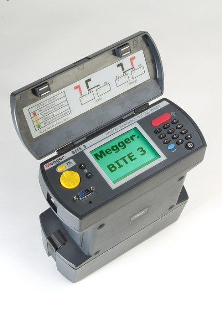
The Megger BITE 3 battery impedance tester determines the condition of lead-acid cells up to 2,000 amp-hours by measuring key battery parameters. The BITE 3 measures cell impedance, cell voltage and cell junction resistance and performs an internal ohmic test. In addition, for the first time in such an instrument, the BITE 3 battery impedance tester measures trickle charge current and superimposed AC current. There is even a built-in spectrum analyzer to display the harmonic content of the AC current. The instrument includes firmware that can be updated using the Internet and supports a variety of languages. The BITE 3 is one of the easiest devices to use. It works by measuring the internal impedance of cells, cell junction resistance, cell voltage, and trickle charge current and ripple current.

These quantities, along with temperature, specific gravity, and other battery data, provide the best means of evaluating the overall condition of the batteries from terminal plate to terminal plate, and to some extent the charger (the superimposed AC current and its harmonic content.) Megger recommends that the BITE 3 be one of the elements of a comprehensive battery maintenance program in which, for lead-acid cells, semi-annual and for VRLA, quarterly
for lead-acid cells and quarterly for VRLA. The BITE 3 is one of the easiest instruments to use.

It operates by measuring cell internal impedance, cell junction resistance, cell voltage, and float charge current and ripple current. These quantities, along with temperature, specific gravity and other battery data, provide the best means of evaluating the overall condition of the batteries. To some extent, also the charger (the superimposed AC current and its harmonic content.) Megger recommends making the BITE 3 one of the elements of a comprehensive battery maintenance program.

We will be happy to advise you on the subject: Battery measurement | Battery testing | Battery capacity test.

Cable location | vLoc3 | Cable measurement

Cable location | vLoc3 | Cable measurement

Cable location | vLoc3 | Cable measurement

vLoc3 line locator series consists of 7 different features and functions: vLoc3-Pro, vLoc3-5000, vLoc3-Cam, vLoc3-9800, vLoc3-ML, vLoc3-RTX-Pro and vLoc3-DM. The vLoc3 series line locator receivers are, in short, the perfect measurement devices for locating underground networks.

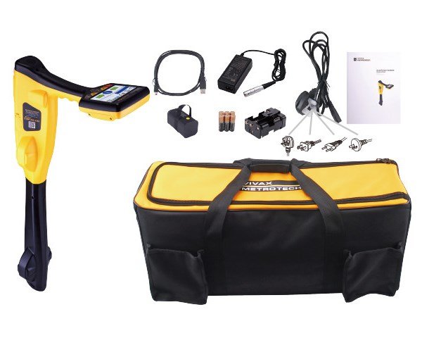
vLoc3-Pro is a locating system for locating underground lines and cables. It enables 3-dimensional line location. And is mainly used in the field of cable measurement technology. It also provides all the necessary information for accurate cable testing and cable fault location. Two sets of 3D antennas detect interference fields. The degree of interference is shown on the display in three different colors. In addition to the familiar classic locating mode, the cable fault locator also has other innovative features. Thanks to the vector screen, the user no longer even has to walk over the cable to check it. This leads to more safety, for example in road traffic.

Moreover, the device contains eight passive locating modes and a sheath fault location function. As well as an SD mode and a frequency range of 98Hz – 200KHz. If the receiver swings too fast, the device alerts the user. Thereby it avoids mislocations. The measuring device also indicates cables laid too flat, field disturbances or interference fields caused by above-ground routes.

vLoc3-5000: The vLoc3-5000 receiver combines Signal Select™ (SiS), Signal Direction (SD), Bluetooth, real-time colour coding and an internal precision GPS module.
vLoc3-Cam: The vLoc3-Cam is the easiest tool when it comes to finding probes (pig transmitters) and camera heads.
vLoc3-9800: The vLoc3-9800 locator is a simple tool for locating underground utilities to prevent damage while gathering information for analysis.
vLoc3-ML is the advanced version of the vLoc3-Pro cable locator. It is the 2-in-1 device for marker and line location and enables precise location of disc and ball markers.

We are happy to advise you on the topics: Cable location | Cable measurement technology | Cable fault location.
VLF Measuring M-VLF60 | Cable Diagnostics

VLF Measuring M-VLF60 | Cable Diagnostics

VLF Measuring M-VLF60 | VLF testing

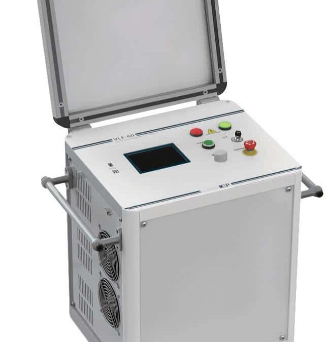
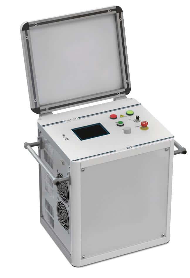
VLF Meter M-VLF60 | Cable Testing | VLF Testers – Testing medium voltage cables with the M-VLF60 is easier today than it was many years ago. A VLF test finds faults in your cable system at much lower voltage than a conventional DC test. Thus, no traveling cells are generated. The M-VLF60 is a compact and, thanks to its robust design, extremely field-proof test system for medium voltage cables. No external PC is required on site. Fast commissioning and the possibility of true continuous operation qualify the unit as an ideal tool for routine cable testing.

With the portable VLF meter M-VLF60 you can test the following cables XLPE, PE & EPR. The VLF tester series finally allows utilities and industry an economical alternative to DC testing. To protect the operator and the equipment, the device has two independent discharging devices and an integrated 12kV reverse voltage protection (50 Hz). Thus, the software allows easy report generation. Also, the fast programming of test sequences. VLF stands for Very Low Frequency, 0.1 Hz and below.

Thus, it is an alternating voltage at low frequency. A VLF test system is simple to operate and the test is easy to perform. Conventional AC voltage test equipment has been used for decades for many types of installations. The test voltage is applied for the desired duration. This is because the DUT holds the voltage and either passes or fails. It is a pass/fail test. Why VLF testing? Because DC tests damage the insulation of the cable. That way, VLF testing shows the damage of the insulation without harming the cable.

We offer you advice on the topics of: VLF meter devices | cable diagnosis | VLF diagnosis.

VLF Measuring M-VLF34 | Cable Test

VLF Measuring M-VLF34 | Cable Test

VLF Measuring M-VLF34 | Cable Test

VLF Meter M-VLF34 | Cable Testing – The field of work of the M-VLF34 is cable testing and cable diagnosis. The high voltage generator is a very compact and very light VLF test instrument. With the variable VLF system, it is possible to select the two polarities accordingly the mode DC testing and the AC output frequency. Cable sheath testing or sheath fault location are part of the selection range. M-VLF34 is a portable generator that generates high voltage to eliminate cable faults.

For the 0.1Hz VLF test system is suitable for medium voltage cable testing. VLF meter type M-VLF34 is a portable system for cable diagnosis and testing. A high output current up to 85mA is considered the special strength of the device. The powerful output is able to drive capacitive loads up to 15 microfarad. Weighing only 45kg, the high voltage generator is a compact VLF unit, making it perfect for mobile use. Due to its light weight, the site of operation can be easily reached.

With a maximum output voltage, it is possible to test a cable with a length of up to 8 km. M-VLF34 can also be extended to a cable diagnostic system due to its full modularity. Also, the system offers different operating modes. A built-in discharging device is available for discharging the DUTs. The M-VLF34 has a manual and automatic test diagnostic sequence. No external PC is required on site. Due to the fact that the VLF measuring device is not thermally limited, it can be operated continuously over the entire operating time.

We offer you advice on the following topics: VLF measuring devices | cable diagnostics | VLF diagnostics.

Time Domain Reflectometer | TDR2000-3 | TDR Meter

Time Domain Reflectometer | TDR2000-3 | TDR Meter

Time domain reflectometer | TDR2000-3

Time Domain Reflectometer: The TDR2000 series has a large, high-resolution, color WVGA display with easily adjustable performance features. Directional control keys along with soft keys make operation intuitive and easy for the user.An AUTO selection option ensures that the most effective parameters are selected based on the required range, supporting rapid diagnosis of TDR tracking. The ability to manually override the Auto function allows fine-tuning and detection of hard-to-detect errors.

The dual tracking and dual cursor capability allows complete flexibility; the operator has complete control and instant distance indication between the two points. The tracking comparison feature also allows for in-depth inspection between tracking conditions. Extra high resolution along with daylight backlighting and user-determinable color schemes give the graphical display a dynamic quality that helps the operator identify key tracking events.

Trace storage: 100 internal trace memories are available for storing and recalling test results. The tracings can be recalled and displayed for analysis or can be compared to an active display to aid in fault location.Alternatively, the stored results can be downloaded to a computer via a USB interface using TracXpert software and the supplied USB cable. Step TDR function:The dead zone effect of a standard pulse TDR can mask defects near the end, making them undetectable. The addition of a step function on the TDR2050 fixes this problem. Step TDR technology means that the signal is impressed at full strength and remains there until a fault is detected. This makes the step TDR technology perfect for detecting faults near the end that are missed by standard pulse TDR.

We will be happy to advise you on the subject of: Time Domain Reflectometer | Fault Detection | Function TDR.

PD150 Fault indication system partial discharge

PD150 Fault indication system partial discharge

PD150 Fault indication system partial discharge

Online partial discharge: The PD150 is a fault alarm system for partial discharges in the control cabinet. With the PD 150 fault alarm system, partial discharge activities within a live switch cabinet can be detected remotely. Partial Discharge is commonly found on aging MV & HV cable accessories. Insulation faults are an important factor in degradation and reduction of the lifetime of an electrical apparatus. This translates into raised exploitation costs and questionable reliability, while economic performance and reliability are key criteria in the evaluation of an electricity supplier.

One of the challenges is to address those secondary substations which are too often overlooked due to their high volume spread in a large territories. The PD-Annunciator is the next generation of partial discharge monitoring system for local or remote deployment at reasonable cost. Its unique design allows for quick and easy DIN rail installation, or directly held on metallic cabinets with its strong magnets. Need to monitore multiple switchgear cabinets?

PD-Annunciator is daisy-chainable for clean installation that requires minimal cabling. The easily available RJ45 cables are in fact all that’s needed to connect modules one another for data communication and power supply. Up to 3 sensors are connected to PD Annunciator. In case of detected PD activity, a local alarm would turn on the corresponding LED indicator and send this same alarm status to SCADA. Next Generation of Online partial discharge: PD-Annunciator is perfectly suited for substation environment, field applications, remote locations, etc. – 20+ years experience in the partial discharge detection and analysis field.